Grounding Brush Types
Differentiating toothbrush & plunger-type brushes
Toothbrush Type Brushes
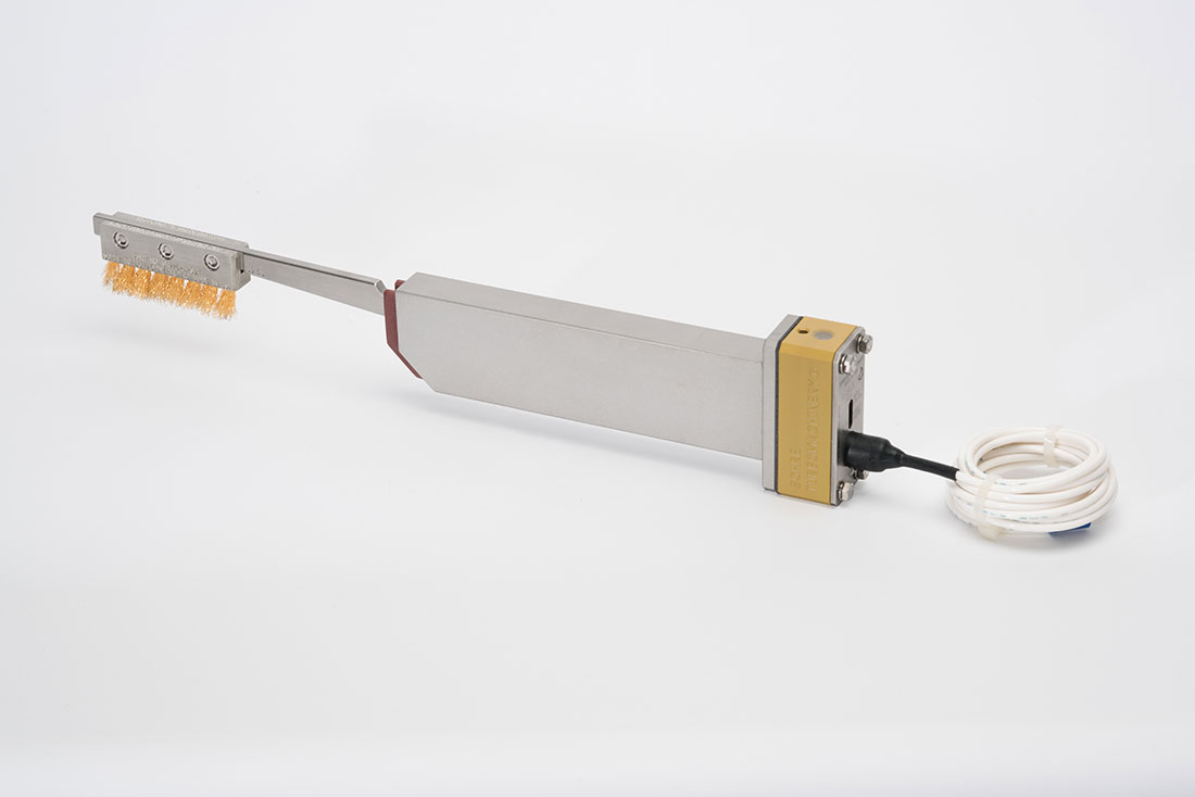
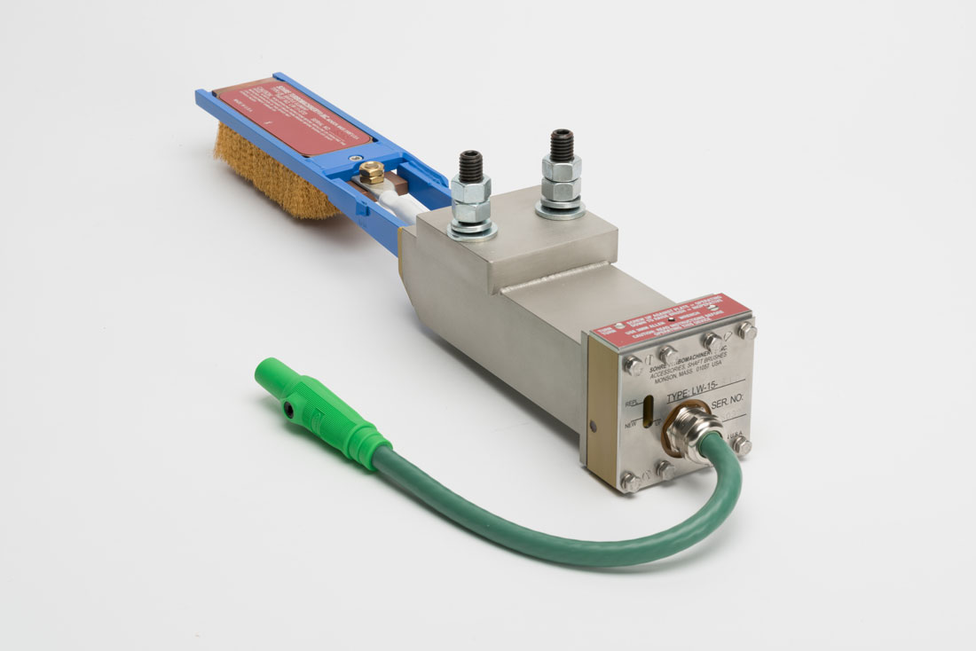
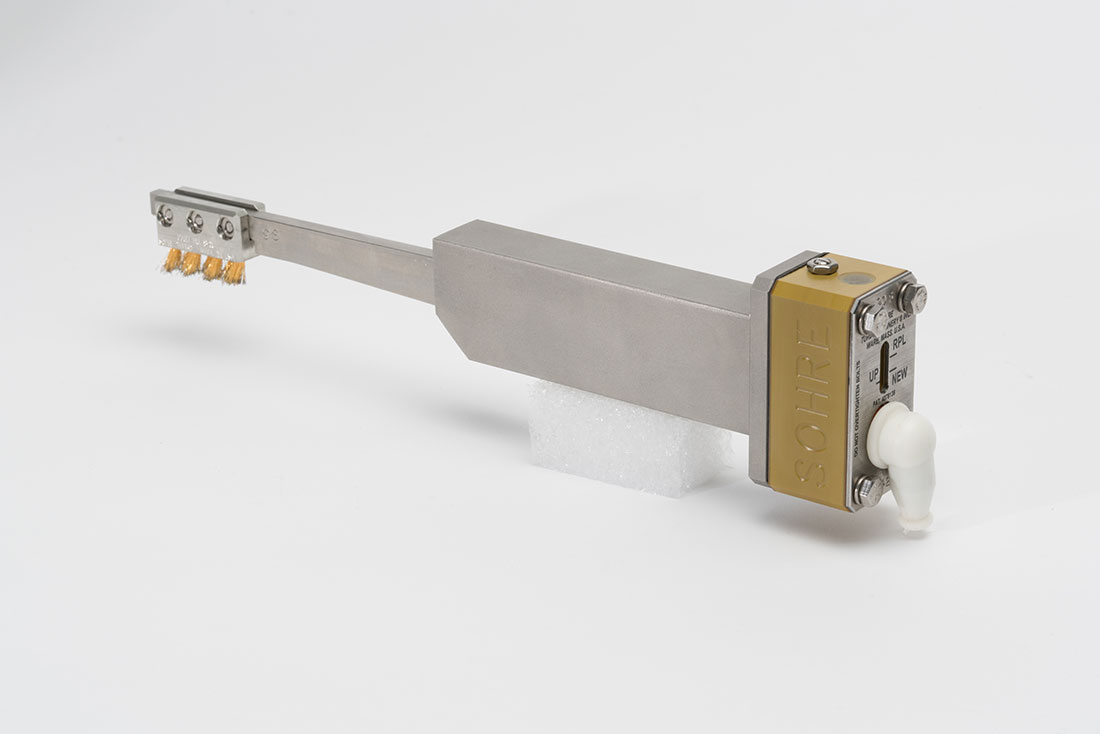
Generally speaking, Type-L and Type-S brushes are suitable for mechanical drive equipment and small turbine-generators. Type-LW brushes are meant for central station power plants with units having labeled ratings of 100 MW to more than 1,000 MW. Of the smaller brushes, the Type-L will carry about four times as much current as a Type-S for the same bristle “burn-off” rate. For this reason, the Type-L is the most economical of the small brushes in terms of ampere-hours per dollar and has the longest bristle element replacement interval of them.
For turbine-generators we suggest the following as a rough guideline for grounding brushes:
Type-L Brushes
Large, narrow shaft-grounding brushes for use inside the frames of turbomachines in process industries, such as air and gas compressors, turbines, pumps, and motors subject to electrostatic-, electromagnetic-, or ground fault-induced stray currents. These brushes also are suitable for smaller turbine-generators and electric motors. They are designed for up to 50 MW per brush, or up to 4 A DC continuous for one year of bristle element life.
Type-LW Brushes
Large, wide shaft-grounding brushes that offer extremely low contact resistance and long life expectancy. Designed for high-current applications (≤100 A), Type-LW brushes are recommended for large turbine-generator rotor shafts as well as for ship propeller shafts and large turbine-generator rotor shafts. Designed for up to 500 MW per brush or up to 100 A DC continuous for one year of bristle element life.
Type-S Brushes
Similar to the Type-L, but for small, high-speed turbomachines in process plants where space is extremely limited but currents are relatively low. Because of the smaller size, this brush is consumed faster than the Type-L for any given current rating. Designed for up to 25 MW per brush or up to 1 A DC continuous for one year of bristle element life.
Actual figures depend very much upon particulars of a given installation, not all of which will be known at the time of brush installation. There are many factors that can have a strong influence on the life expectancy of the sacrificial bristle elements. Examples include residual magnetism in shafts and casings or the design and condition of a motor or generator and exciter. At higher currents, the rate of bristle burn off increases significantly, but this is not yet well understood or predictable.
The number of brushes required per turbine generator unit varies with machine design and operational requirements. Rule of thumb: Use one Type-LW brush per 250 MW, but it will be necessary to match the brush to the stray current output by means of experimenting with shunt resistors. A 1,500-MW unit would require six brushes, for example. Even if only one brush is required (on a 250-MW machine), it is nevertheless advantageous to use two brushes because a pair provides foolproof service and no loss of ground protection when one of the brushes is removed for maintenance. Also, a pair of brushes eliminates the likelihood of sparking if a problem develops (still only 1-2 V would be on the shaft with only one operating brush). Paired brushes may be installed side-by-side or end-to-end on the same track.
Plunger Type Brush
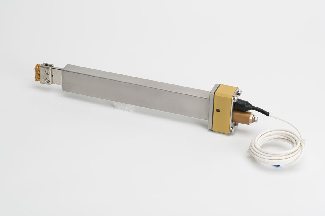
The Type-A brush is especially suitable for axial installation against a shaft-end or collar. This often is the only accessible location in field retrofits, especially if the brush is to be installed in the end plate of the bearing case while the machine is operating. However, this brush is also well suited for radial shaft contact. They are designed for up to 25 MW per brush or up to 1 A DC continuous for one year of bristle element life.
All four shaft-grounding brush types can be mounted to ride on a shaft tangentially, radially, axially or skewed in any position with respect to rotation including upside-down (for example, against the bottom of the shaft).
All types are available from stock in varying standard lengths to suit mounting conditions. Presently, the shortest assembly is 6″ long; the longest is 20″. The brush element is 0.6″ wide for Type-L, Type-S, and Type-A shaft-grounding brushes. The Type-LW brush element is 2.0″ wide.
Additional Considerations
Note: Only the arm and casing length vary for a given model within each type. The bristle element size and all other dimensions remain the same. For example, all Type-L brushes use the same bristle element.
If a turbine generator’s duty cycle involves frequent start/stops or extensive operation at 2/3 rating or less, many units will generate significantly more stray electrical shaft current during such operation. How much more is unpredictable. As a rough guide for such situations, we suggest using only 2/3 of the above mentioned power rating per brush guidelines; otherwise the rate of bristle depletion due to electrical burn-off can be unacceptably high. Units with modern excitation systems are more likely to generate strong shaft currents, as are certain design types by some generator manufacturers.
An increase in residual magnetism inside a turbine or compressor can lead to increased current through grounding brushes and a more rapid bristle depletion rate due to electrical burn-off. Rubs, nearby lightning strikes, welding done in the neighborhood of the equipment without properly grounding the welding machine to the work-piece, and surges (in compressors) are examples of ways in which residual magnetism inside a machine can increase.
Similarly, the amount of shaft current due to static charge buildup can increase during operation, resulting in an increased bristle burn-off rate. Common causes are blocked casing and pipe drains (in turbines or compressors), wet steam due to operation at low load (steam turbines), water droplet injection (wet compression) into a gas turbine compressor inlet for power augmentation on hot days, and certain operating configurations on variable extraction steam turbines.
In the case of mechanical drive turbomachinery, the above power rating per brush suggestions also roughly apply to turbo compressors and other turbomachinery as found, for example, in petrochemical plants. For such equipment, it often is possible to get an estimate of the necessary size and number of grounding brushes by computing the sum of the rating of all the potential drivers in a train (turbines, expanders, motors, etc.). Because protecting a train of mechanical drive turbomachinery is a complicated issue, we suggest contacting us for guidance when considering a shaft grounding arrangement for such equipment.
Operation in potentially explosive environments is another reason for installation of grounding brushes at both ends of a shaft. Moreover, installation of two grounding brushes, running in the same rotor track wherever brushes are installed is suggested in the case of operation in such environments (there are also other possible mitigation methods).
Important: We suggest contacting Sohre Turbomachinery® for guidance if there is a possibility that brushes will be operated in a potentially explosive environment.
The quantity and model of shaft-grounding brush best used on a particular unit depends on the maximum amount of peak current to ground, as well as physical constraints. The amount of current is difficult to predict since it depends on factors such as the strength of residual magnetism in the machine (particularly in rotor, stator, foundation, piping, etc.). With electrical equipment, generator and exciter design or condition are also very important. Drawings Location, Arrangement, L Installation, and A Installation give general guidance on where to install brushes, along with typical installation configurations. Be sure to contact us if you have any question as to how to proceed.


